Powered by Blogger.

Total Pageviews

I m on Twitter!

Sunday, March 25, 2012

Low pass filter for subwoofer


Many low pass filter circuits for subwoofer are given here and this is just another one. The circuit given here is based on the opamp TL062 from ST Micro electronics. TL062 is a dual high input impedance J-FET opamp which has very low power consumption and high slew rate. The opamp has excellent audio characteristics and is very suitable for this circuit.


Out of the two opamps inside TLC062, first one is wired as the mixer cum pre amplifier stage. The left and right channel are connected to the inverting input of IC1a for mixing. The gain of first stage can be adjusted using POT R3.The output of the first stage is connected to the input of second stage through the filter network comprising of components R5,R6,R7,R8,C4 and C5. The second opamp (IC1b) serves as a buffer and the filtered output is available at the pin 7 of the TLC062.
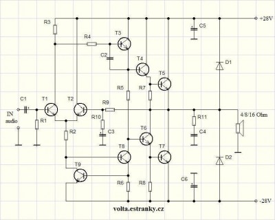


Circuit Diagram :


Power Suppy for Circuit :


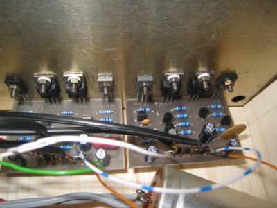
Above Firgures Show How to make an Subwoffer Sound Producer.


Thanks :)))


The Palace Builder v1.0.1.101


In 18th century France, you are a young, unknown architect looking for your big break and a chance to impress the Queen. In this building Simulation game, set in the romantic upper class world of French aristocracy, you will design and manage the construction of the most beautiful structures in the kingdom. Will your work attract the attention of the Queen, or will a secret destroy your chances for fame and fortune? Find out in The Palace Builder

Download

Counter Strike 1.6


Game Play Video


Minimum: 500 mhz processor 96mb ram, 16mb video card, Windows 2000/XP/ME/SE, Mouse, Keyboard


Download Links >>>


GTA 4 Full Game Download (15.61GB)


Game Play Video


System Needs:


Minimum system requirements:

Operating system: Windows Vista-Service Pack 1/XP-Service Pack 3/Win7

Processor: Intel Core 2 Duo 1.8 Ghz, AMD Athlon X2 64 2.4 Ghz

RAM: 1.5 GB Vista, 7 / 1 GB XP

Free space on your hard disk: 16 GB

Video Card: 256 MB Nvidia 7900 / 256 MB ATI X1900

Sound device: compatible with DirectX ® 9.0c


Installation instructions of GTA4:

To install the required software to emulate a disk. Installation is in 4 stages:

Set yourself modes (specify a directory for the game itself)

Set over patch 1.0.4.0 (to establish himself, no matter where lies)

Ustanalvivaem Russifier (on request, as well as the patch is installed regardless of where lies)

Copy the crack from Razor folder in the directory with the game


Download Link (Total size 15.61GB)


Call Of Duty 4 Modern Warfare


Game Play Video


Min. System Requirements :CPU: Intel(R) Pentium(R) 4 2.4 GHz or AMD(R) Athlon(TM) 64 2800+ processor or any 1.8Ghz Dual Core Processor or better supported
RAM: 512MB RAM (768MB for Windows Vista)
Harddrive: 8GB of free hard drive space
Video card (generic): NVIDIA(R) Geforce(TM) 6600 or better or ATI(R) Radeon(R) 9800Pro or better.


Download Links >>>


Saturday, March 24, 2012

IDM 6.10 Build 8 FINAL FUll with Patch Tool Life Time | 4.6 MB | Mediafire

This is the latest version of IDM released a few days ago for those of you who want to have IDM v6.10 Build 8 Final please donwload at the link below. It is certain at this time many additional versions of the IDM v6.10 Build 8 Final, for those of you who are already using IDM already know what the benefits of this software, the obvious advantages of this software to speed up the process of downloading files on the internet.


                       Download: IDM 6.10 Build 8 FINAL | Here |


Direct Download:
Cant click then copy paste in address bar......


Fet Buffer for amplifiers


source: http://cappels.org/dproj/edfet/edfet.html

The EDFET drives like a FET, but with the bias stability of bipolar. Amps of output current can be controlled by milliamps of input current. The current gain is a design choice dictated by bandwidth. Two of things you have to consider when adding a power output stage to an op-amp circuit are the frequency response and the cross-over distortion in that stage.

This is especially true with wide band amplifiers, where the unity gain crossover needs to be at several hundred kilohertz. The stage is driven much the same as a complimentary pair output stage, but with the current gain that comes with using FETs., and with feedback within the output stage that that extends the buffer's bandwidth and regulates the quiescent current. More predictable operation allows the designer to design a circuit lower overall power dissipation and better closed loop stability.


Fet Buffer for amplifiers


The EDFET complimentary buffer is made up of a pair of unity gain buffers, one that drives in the positive direction and the other that drives in the negative direction. Pictured above is the positive driving half of the output stage.

Gain to make the output signal track the input signal comes from inverting transistor, Q1. The input signal is applied to the emitter of Q1 and the output of the amplifier is raised one diode drop to match the forward base-emitter drop of Q1, by diode connected transistor Q2. The buffer's offset is determined by the log of the magnitude of the mismatch in the emitter currents in Q1 and Q2, and it is directly proportional to the absolute temperature.

Since the saturation current usually isn't published for the transistors this expression is only usefully for appreciating the dependence of junction voltage on current and temperature. You can come up with your own value of I0 for a given transistor if you know all the other parameters and solve the above formula for I0. By the way, since, for most practical uses, you will be running at more than a thousand times the saturation current, the "+1" term can be dropped from practical calculations.

As an example, for the audio amplifier using a EDFET buffer shown in Figure 1. The following assumptions are applied: The maximum output voltage is 5 VDC with respect to ground, the power supply (VA) is 12 VDC, the maximum gate voltage is 8 VDC, the input capacitance, Ciss of the BUZ73 is 500 pf, and an...
http://cappels.org/dproj/edfet/edfet.html

Discrete Buffer: Diamond Buffer
Discrete Buffer: JISBOS Buffer

50 watts transistor amplifier


The amplifier and speakers that can handle medium-power is designed to provide a strictly amateur. Accidental overloads can damage the speakers, it is not appropriate for small systems.

What amp settings do not contain an element of the first connection wiring must be careful to work with.
Characteristics of the transistor, the fan or heat sink is cooled enough to find out if you need to focus!

Tech. parameters:
Power: + - 28V
Power: 50W / 4 ohms
Input sensitivity: 250mW of
Input resistance: 50 kOhm
Frequency range: 30Hz to - 30kHz

Optimal mobile recording portable player to another amplifier Multi Media.


Here, the schematics this power amplifier


List of components:
R1, R2, R9 - 56K
R3 - 3K3
R4, R6 - 100R
R5 - 220R
R7, R8 - 120R
R10 - 1K
R11 - 1R
C1 - in 1µF / 35V
C2 - 33P - Ceramics
C3 - the 100µF/35V
C4 - 100 N (220N) - Ceramic
C5, C6 - 4.7 UF / 35V
D1, D2 - 1N4007
T1, T2, T9 - BC546
Q3 - BC640
T4 - BD139
T5, T7 - BD711
T6 - BD140
T8 - BC639

Following the DC voltage amplifier and limiter speaker protection is needed.


Pro Evolution Soccer


Game Play Video


Minimum requirements
Intel Pentium 4 1.4GHz or equivalent

 512 MB RAM

NVIDIA GeForce 3 or

ATI Radeon 8500 video card or better
Recommended:
Pentium 4 3.0GHz/AMD Athlon 64 or better

1GB RAM, ATI x1600 or 

NVidia 6800 GT/GS or better


Download Links >>>


Very Simply 10 Watts Stereo Power Amplifier-TDA2009A


Here are a power amplifier with TDA2009A integrated circuits produced by 10 +10 W stereo amplifier (see figure). As a result of ASIC, making her the production becomes very simple, the performance is not bad.

Her main performance characteristics in the table below.


Power Supply Voltage: DC 8-24V/1-2A
Power Output:


  1. 10W RMS / channel, 4 ohm load, 24V/DC power;
  2. 6W RMS / channel, 8 ohm load, 24V/DC power;
  3. 4W RMS / channel, 4 ohm load, 12V/DC power.

S/N: >75dB/10W output
Frequency response: 10Hz-50kHz,-3dB
Gain: 36dB
Input Level: 100mV Full output power

Schematic and Prototype:


Principle and production elements:


C1, C2 as the input capacitor, C10, C11 for the output capacitor. C6, C7 for the feedback capacitance. R1/R2, or (R3/R4) control the amount of feedback. Amplifier gain is equal to 1 + (R1/R2) = 68, or 37dB. C4, C5 for the power supply filter capacitor. The device maximum supply voltage of 28V. Hours of work required to add TDA2009A heat sink, and should pay attention to the power lines and then the choice of speaker wiring. Input should use shielded lines and as short as possible. Welding TDA200A not take too long when you pay attention, action to be fast, but if you want their full integration with the circuit board.

Ads By Sponsers