A thermocouple is a device made by two different wires joined at one end, called
junction end or
measuring end. The two wires are called
thermoelements or legs of the thermocouple: the two thermoelements are distinguished as positive and negative ones. The other end of the thermocouple is called
tail end or
reference end. The junction end is immersed in the environment whose temperature T
2 has to be measured, which can be for instance the temperature of a furnace at about 500°C, while the tail end is held at a different temperature T
1, e.g. at ambient temperature.
Figure 1.
Because of the temperature difference between junction end and tail end a voltage difference can be measured between the two thermoelements at the tail end: so the thermocouple is a temperature-voltage transducer.
The temperature vs voltage relationship is given by:
Equation 1
Where Emf is the Electro-Motive Force or Voltage produced by the thermocople at the tail end, T1 and T2 are the temperatures of reference and measuring end respectively, S12 is called Seebeck coefficient of the thermocouple and S1 and S2 are the Seebeck coefficient of the two thermoelements; the Seebeck coefficient depends on the material the thermoelement is made of. Looking at Equation1 it can be noticed that:
- a null voltage is measured if the two thermoelements are made of the same materials: different materials are needed to make a temperature sensing device,
- a null voltage is measured if no temperature difference exists between the tail end and the junction end: a temperature difference is needed to operate the thermocouple,
- the Seebeck coefficient is temperature dependent.
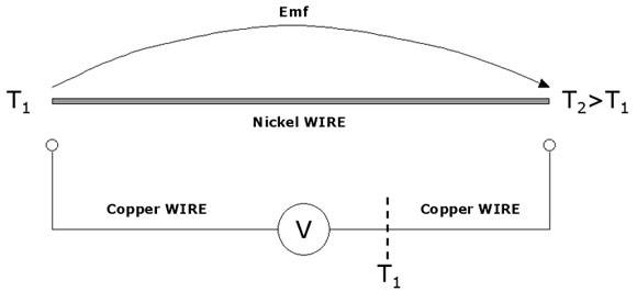
In order to clarify the first point let us consider the following example (Figure2): when a temperature difference is applied between the two ends of a single Ni wire a voltage drop is developed across the wire itself. The end of the wire at the highest temperature, T2, is called hot end, while the end at the lowest temperature, T1, is called cold end.
|
Figure2: Emf produced by a single wire |
When a voltmeter, with Cu connection wires, is used to measure the voltage drop across the Ni wire, two junctions need to be made at the hot and cold ends between the Cu wire and the Ni wire; assuming that the voltmeter is at room temperature T1, one of the Cu wires of the voltmeter will experience along it the same temperature drop from T2 to T1 the Ni wire is experiencing. In the attempt to measure the voltage drop on the Ni wire a Ni-Cu thermocouple has been made and so the measured voltage is in reality the voltage drop along the Ni wire plus the voltage drop along the Cu wire.
The Emf along a single thermoelement cannot be measured: the Emf measured at the tail end in Figure1 is the sum of the voltage drop along each of the thermoelements. As two thermoelements are needed, the temperature measurement with thermocuoples is a differential measurement.
Note: if the wire in Figure2 was a Cu wire a null voltage would have been measured at the voltmeter.
The temperature measurement with thermocouples is also a differential measurement because two different temperatures, T1 and T2, are involved. The desired temperature is the one at the junction end, T2. In order to have a useful transducer for measurement, a monotonic Emf versus junction end temperature T2 relationship is needed, so that for each temperature at the junction end a unique voltage is produced at the tail end.
However, from the integral in Equation1 it can be understood that the Emf depends on both T1 and T2: as T1 and T2 can change indipendently, a monotonic Emf vs T2 relationship cannot be defined if the tail end temperature is not constant. For this reason the tail end is mantained in an ice bath made by crushed ice and water in a Dewar flask: this produces a reference temperature of 0°C. All the voltage versus temperature relationships for thermocouples are referenced to 0°C.
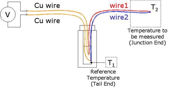
The resulting measuring system required for a thermocople is shown in Figure3.
|
Figure3: A measuring system for thermocouples |
In order to measure the voltage at the tail end, two copper wires are connected between the thermoelements and the voltmeter: both the Cu wires experience the same temperature difference and as a result the voltage drops along each of them are equal to each other and cancel out in the measurement at the voltmeter.
The ice bath is usually replaced in industrial application with an integrated circuit called cold junction compensator: in this case the tail end is at ambient temperature and the temperature fluctuations at the tail end are tolerated; in fact the cold junction compensator produces a voltage equal to the thermocouple voltage between 0°C and ambient temperature, which can be added to the voltage of the thermocouple at the tail end to reproduce the voltage versus temperature relationship of the thermocouple.
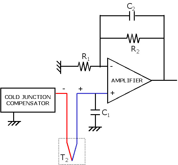
A sketch of a thermocouple with cold junction compensation is reported in Figure4.
|
Figure4: An example of Cold Junction Compensation |
It should be underlined that the cold junction compensation cannot reproduce exactly the voltage versus temperature relationship of the thermocouple, but can only approximate it: for this reason the cold junction compensation introduces an error in the temperature measurement.
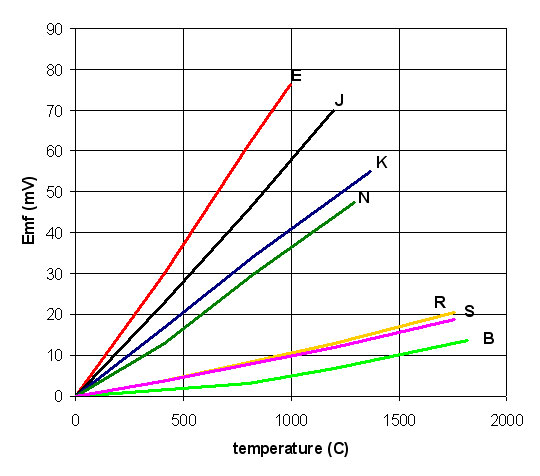
Figure4 shows also the filtering and amplification of the thermocouple. Being the thermocouple voltage a DC signal, removal of AC noise through filtering is beneficial; furthermore the thermocouples produce voltage of few tens of mV and for this reason amplification is required. The small voltage range for some of the most common thermocouples (letter designated thermocouples) is shown in Figure5, where their voltage versus temperature relationship is reported.
Type R, S and B thermocouples use Pt-base thermoelements and they can operate at temperatures up to 1700°C; however they are more expensive and their voltage output is lower than type K and type N thermocouples, which use Ni-base thermoelements. However, Ni base thermocouples can operate at lower temperatures than the Pt-base ones. Table1 reports the approximate compositions for positive and negative thermoelements of the letter designated thermocouples.
|
Figure5: Voltage vs Temperature relationship for letter-designated thermocouples |
|
Thermocouple type |
Positive Thermoelement |
Negative Thermoelement |
B |
Pt-30%Rh |
Pt-6%Rh |
R |
Pt-13%Rh |
Pt |
S |
Pt-10%Rh |
Pt |
K |
Ni-10%Cr |
Ni-5% other elements |
N |
Ni-14%Cr-1.5%Si |
Ni-4.5%Si-0.1%Mg |
E |
Ni-10%Cr |
45%Ni-55%Cu |
J |
Fe |
45%Ni-55%Cu |
|
Table1: Approximate composition for thermoelements of letter-designated thermocouples |
All the voltage-temperature relationships of the letter designated thermocouples are monotonic, but not linear. For instance the type N thermocouple voltage output is defined by the following 10 degree polynomials, where t is the temperature in degree Celsius:
 |
Equation2 |
The coefficients Ci are reported in Table2.
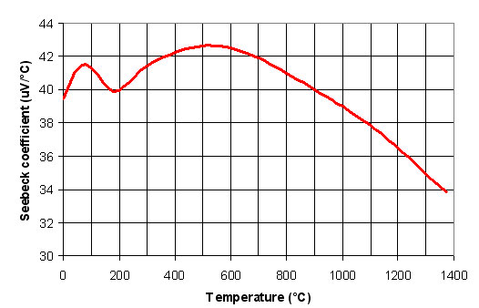
In order to have a linear voltage-temperature relationship the Seebeck coefficient should be constant with temperature (see Equation1); however the Seebeck coefficient is temperature dependent, as shown for instance for type K thermocouple in Figure6. Additional details on the voltage-temperature relatinships for letter designated thermocouple can be found at:
Coefficient |
Temperature range: (-270°C,0°C) |
Temperature range: (0°C,1300°C) |
c0 |
|
|
c1 |
0.261591059620 x10⁻¹ |
0.259293946010 x10⁻¹ |
c2 |
0.109574842280 x10⁻⁴ |
0.157101418800 x10⁻⁴ |
c3 |
-0.938411115540 x10⁻⁷ |
0.438256272370 x10⁻⁷ |
c4 |
-0.464120397590 x10⁻¹⁰ |
-0.252611697940 x10⁻⁹ |
c5 |
-0.263033577160 x10⁻¹¹ |
0.643118193390 x10⁻¹² |
c6 |
|
-0.100634715190 x10⁻¹⁴ |
c7 |
|
0.997453389920 x10⁻¹⁸ |
c8 |
|
-0.608632456070 x10⁻²¹ |
c9 |
- |
0.208492293390 x10⁻²⁴ |
c10 |
- |
-0.306821961510 x10⁻²⁸ |
|
Table2: Type N thermocouple coefficents |
|
|
|
|
|
|
|
Figure6: Type K Seebeck coefficient vs Temperature |


