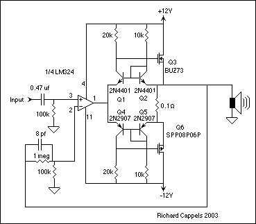
Heavy load capacitance can cause the output of a unity-gain follower—an operational amplifier with direct feedback to the inverting input (
)—to ring and oscillate. The LM110 follower, for example, normally drives a 50-pF load without problems, but it does not drive 500 pF stably—high capacitance significantly modifies the open-loop output impedance, reducing the phase margin to zero and causing oscillation.
You can easily eliminate such instability problems by adding a capacitor and resistor in series across the op amp's inverting and noninverting inputs. This solution can also greatly improve a follower's slew rate.
Analyze the problem
In general, increasing the ac noise gain of an op amp's feedback network improves capacitive-load tolerance. A common gain-increasing strategy adds R
2~R
F/10 to the circuit shown in
Fig 2. (A moderate-value capacitor, C
2, usually inserted in series with R
2, prevents the dc noise gain from also increasing and degrading dc-offset, drift and accuracy specifications.)
If the op amp has a 1-MHz gain-bandwidth product and R
1=R
F, the closed-loop frequency response will be 500 kHz. Inserting R
2=R
F/10 drops this frequency response to 90 kHz, where the amplifier usually tolerates a much larger capacitive load. AC noise gain equals (R
F/ R
1)+(R
F/R
2)+1, and dc noise gain is (R
F/R
1)+1.
You can also increase ac noise gain by installing R3 and C3 instead of R2 and C2. The resulting value is
[1+(RF/R1)][(R++R3)/R3]+(RF/R3).
In the simplest case, R
1 forms an open circuit, and ac noise gain equals
(R+/R3)+(RF/R3)+1.
Therefore, you can raise ac noise gain by using a low value for R
3 and a high value for R
+ and/or R
F.
The solution followsFor the particular case of a unity-gain follower, RF is normally 0O as shown in Fig 3. According to the foregoing general analysis, if the value of RS is low, ac noise gain is (R4/R5)+1, so you can increase ac noise gain—and therefore stability—by adding a large R4 and a small R5. (A large and constant RS can make R4 unnecessary; ac noise gain is then (RS/R5)+1.)
With LM110/LM310s, for example, 10k is an appropriate value for R4. Using R5 = 3.3k and C5 = 200 pF, the LM110 stably drives capacitive loads up to 600 pF.
Technique speeds followersYou can also wire the resistor/capacitor combination across an op amp's inputs to increase the follower's slew rate. For example, an LF357 op amp's decompensation with a small internal capacitor normally requires gains higher than five to maintain stability (
Fig 4). But the LF357 fits unity-gain-follower applications as easily as the LF356 (which is identical to the 357 except for the 356's internal compensation) and achieves better results. When source resistance is less than 1k, both the LF357 and 356 provide fast, stable responses, but the 357 has a 50V/µsec slew rate (typical) compared with 12V/µsec for a 356.
The LM349 decompensated quad op amp furnishes a bipolar input stage with a finite bias current (200 nA max). For best results in this application, add the resistor that controls the noise gain equally to the inverting and noninverting inputs as shown in Fig 5. With this circuit, the LM349 can slew at 2V/µsec typ and handles audio signals much faster—and without distortion—than the compensated LM348 (which, at 0.5V/µsec, slews only as fast as the general-purpose LM741). You can use the same approach for an LM101 by employing a 5-pF damping capacitor.
Watch for problemsWhile inserting a resistor/capacitor combination across the inputs gives faster slewing, the circuit's bandwidth could degrade if source impedance (R
S) increases. In addition to guarding against bandwidth problems, make sure ac noise doesn't reach an objectionable level when you raise ac noise gain. Although most modern op amps exhibit low noise, raising that noise gain to 10 can significantly increase output noise.
If the series capacitor across the op amp's inputs is larger than necessary for stability and high slew-rate purposes, noise increases unnecessarily. In general, choose the minimum capacitance for the circuit in Fig 3 according to the following formula (where fV = op amp's unity-gain bandwidth):
C
5min = 4[1+(R
4/R
S)]/2pR
5f
V=(R
4+R
5)/(p/2)f
V(R
5)
2. To allow for tolerance variations, make C
5's circuit value two or three times C
5min.
source: http://www.edn.com/article/518641-Improved_unity_gain_follower_delivers_fast_stable_response.phpThe amplifier and speakers that can handle medium-power is designed to provide a strictly amateur. Accidental overloads can damage the speakers, it is not appropriate for small systems.


